
The Bunnings Workshop community can help with your home improvement projects.
- Bunnings Workshop
- >
- How To
- >
- How to build an arcade games cabinet
How to build an arcade games cabinet
Share
- Subscribe to RSS Feed
- Mark as New
- Mark as Read
- Bookmark
- Subscribe
- Printer Friendly Page
- Report Inappropriate Content
.png")
Difficulty: Expert
An arcade cabinet can provide countless hours of fun for all ages. You can play classic video games for a hit of nostalgia or the latest releases.
This step-by-step guide will show you how to build a full-size retro-style arcade cabinet. It includes a comprehensive plan that you can refer to for measurements. We installed a 32-inch widescreen monitor which determined the dimensions of our cabinet. You can obviously install a smaller or bigger screen, and use whatever is your preferred gaming hardware and software inside the cabinet.
As this project involves powered equipment, please follow all safety guidelines provided by manufacturers and use the recommended protective gear.
Let us know if you have any questions. We’d be happy to assist and would love to see your own arcade games cabinet builds.
Steps
Step 1
Mark out the cabinet segments on MDF panels.
Refer to the plans provided below for measurements. Mark out these measurements on your MDF panels using a tape measure. Pay particular attention to marking diagonal lines and their intersection points.


Step 2
Cut the cabinet panels.
Use a circular saw to cut out all the marked segments on the MDF panels, including the cabinet's top, rear, side, front, and base segments. Make sure to clamp down and secure the panels before cutting. Don't forget to use protective eyewear and a dust mask.
Note that the cabinet's base and side segments have square edges. The front facade and hood of the cabinet require angular cuts. Square cuts are required for joining the side segments. I recommend cutting all square cuts first and then re-cutting where required to create the angles.


Step 3
Round the edges of the cut side segments.
Using a router and rounding bit, round over the edges of the cut side segments. As in the previous step, clamp down and secure the side segments before routing. Use protective eyewear and dust mask.


Step 4
Attach the back, front, base and side segments of the cabinet to create a frame.
Using a drill driver and countersink bit, place pilot holes around the side segments' edges as seen in the first image below. Space the holes 100mm apart and place them 8mm from the edge.
Apply PVA glue to the edges of the rear and base segments. Now clasp the two segments firmly using Sash clamps. Screw the segments together using a drill driver and 50mm timber screws as per the second photo below.
While waiting for the glue to dry, apply timber filler over the screws to fill the countersunk holes. You can see the filler applied in image three.
Continue this process until you have attached all the panels together to create a cabinet frame. Once done, flip it to a standing position and ensure it is steady.


Step 5
Attach the cabinet's top segments.
Repeat the instructions in Step 4 and connect the top segments of the cabinet together to create a separate section in the top of the cabinet frame. This section of the cabinet will contain the monitor and marquee.
Apply PVA glue to the edges of all cut top segments and screw into place.


Step 6
Create an access panel door in the cabinet's rear segment.
Mark out a rectangle measuring 550 x 700mm with rounded corners in the lower back half of the cabinet.
Use a jigsaw to cut the marked rectangle as shown in the first two images below. The cut-out rectangular piece will be the access door. The rectangular hole in the cabinet is the door panel. Sand the edges of both the door and door panel to remove any coarse timber.
Next, use a drill driver and 16mm timber screws to fix four hinges to the side of the door and door panel. Connect them together. Ensure that the door opens and closes smoothly.
Now add one side of your magnetic cabinet latch on the door by screwing through the door with your 16mm screws. The other side of the latch is attached to the cabinet's rear segment in a corresponding location so the two will meet when the door is closed.
Finally, drill a 25mm holein your door opposite the hinges using your spade bit. This is the fingerhole that opens the door.


Step 7
Install castor wheels in the cabinet's base segment.
Flip the cabinet on its side and mark the locations for installing castor wheels in all four corners of the cabinet's base segment.
Now use a drill driver to drill 6mm holes through the base. Attach four castor wheels using M6 bolts, washers and nuts. Tighten the nuts with an adjustable spanner.

Step 8
Drill the button holes in the control deck.
For this step, you'll need a template of your button and controller positions. There are many different options and your choice might be affected by your hand size and the types of games you like to play.
The control deck protrudes inside the cabinet, providing a surface for the monitor to rest on. Refer to the provided plans for the position and size of the control deck.
Once you've cut out the segments for the control deck as instructed in Step 1, place a control button positioning template on the deck. Secure it in place with masking tape. Now use the tip of a 25mm spade bit and mark the drill locations for the buttons. Remove the template and drill the marked holes with the 25mm spade drill bit as per the final image below.


Step 9
Create the monitor frame.
Once you've cut out the segments for the monitor frame as instructed in Step 1, carefully remove the monitor from its packaging and place it face down on the cut MDF segment. Trace the perimeter of the monitor screen. Remove the monitor and keep it in a safe place.
Now mark a secondary line 10mm in from the traced line. This will be the cut line. The frame is intentionally built slightly smaller than the monitor to ensure the screen doesn't fall out.
Cut out the monitor frame. Install it in the cabinet's top half by screwing through the cabinet's side panels. It can be easier to do this from inside the cabinet. Screw up through the control panel and into the base of the monitor frame.
Note that the monitor will be tilted backwards to ensure an optimum viewing angle, so ensure the segment directly above the monitor frame is angled appropriately.


Step 10
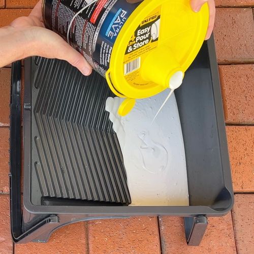
Prime and paint the cabinet.
Apply two coats of primer to the cabinet. Wait for the first coat to dry before applying the second.
Once the primer is dry, you can apply two coats of the topcoat.


Step 11
Install brackets for the monitor screen and test-fit the monitor.
Measure 15cm of your mending bracket. Bend it at the 5cm mark and again in the opposite direction at the 10cm mark. This will create an S-shaped bracket. Adjust your bracket’s shape accordingly to suit your monitor. Create four brackets in total.
Affix two of these brackets on either side of the monitor frame using a drill driver and 16mm timber screws. The remaining two will be used to fix the top of the screen later.


Step 12
Install the marquee display.
Cut a rectangle from the acrylic sheet using a circular saw. Make sure the rectangle is slightly bigger than what you need for the marquee opening. You can then easily sand the edges back to get a perfect fit.
Run a thin bead of silicone around the perimeter of the acrylic rectangle to secure it into the cabinet.
Next, fix an LED batten light to the rear wall of the cabinet, so it is facing the front marquee acrylic sheet. Follow the instructions on the label for installing the light.
Finally, print your design for the marquee and secure it to the rear of the acrylic sheet with tape. You should now have an illuminated marquee display.


Step 13
An optional step (depending on whether your monitor has sound output) is to install speakers in the cabinet. We chose to install speakers and grilles just above the monitor for "in-your-face" sound.
Drill two holes measuring 100mm in diameter directly under the marquee using your hole saw. Screw the 100mm speaker grilles over the holes.
Next, make a hole in one end of Velcro tape. Place a screw in it and then screw it inside the lower section of the marquee behind the speaker hole.
Secure the speakers behind the grilles using the Velcro tape.


Step 14
Install the control buttons.
Wire the control buttons in the cabinet as per their instructions. Make sure to follow all listed safety precautions.
An optional coin slot can also be added by cutting the cabinet's front panel.


Step 15
Mount the monitor and power-up your cabinet
Once the controls are installed, mount the monitor and secure the top in place with the two brackets created earlier. Ensure the monitor is secured. Do not overly compress the screen. Make sure that only the monitor's perimeter is touching the front screen frame.
Place your chosen hardware inside the cabinet and connect all controls. Power-up your components using a power board.
Your arcade games cabinet is now ready for use. Have fun.


Materials
- Five panels of 16mm MDF measuring 2400 x 1200mm
- One 2400mm length of 40 x 18mm Tasmanian Oak DAR
- Standard sanding sheets
- PVA glue 500mL
- Timber filler
- Undercoat 1L
- Black water-based enamel paint 1L
- Masking tape
- Four 25 x 20 x 1.6mm brass butt hinges
- Magnetic cabinet catch
- Four 75mm swivel castors
- 16 x M6 bolts x 25mm, washers and nuts
- Timber screws 4G x 16mm 45 pack
- Two packets timber screws 8G x 50mm 100 pack
- Four pieces mending plate Make-A-Bracket
- Clear acrylic sheet 900 x 600 x 5mm
- One tube clear silicone
- 100mm speaker grilles (optional depending on choice of monitor and sound output)
- Velcro hook and loop tape 1000mm (optional - for securing speakers)
- LED batten light 20W (optional - for lighting up marquee)
- Your preferred electronics such as monitor, computer, speakers and powerboard.
Tools
- Circular saw
- Jigsaw
- Drill driver
- 25mm spade drill bit
- Router
- Sander
- Paint roller and tray
- Paintbrush
- Pilot drill countersink bit
- 5mm rounding over router bit
- 6mm drill bit
- 900mm sash clamps
- 100mm hole saw
- Adjustable spanner
- Carpenters square
- Safety glasses
- Dust mask.
Images


You must be a registered Workshop community member to comment. Please join Workshop or sign in to join in the discussion.
Why join the Bunnings Workshop community?
Workshop is a friendly place to learn, get ideas and find inspiration for your home improvement projects
You might also like


We would love to help with your project.
Join the Bunnings Workshop community today to ask questions and get advice.